Control an LED from Beaglebone GPIO
This tutorial will show you the basics of controlling a GPIO pin on the Beaglebone Black for digital output. It will explain how to export the GPIO pins ready for use, and how to control the pins by manipulating the file system. Later tutorials will build upon this to control the GPIO pins from a programming language such as Python or C++.
To follow along you will need the following
- A Beaglebone Black
- 2A 5volt power supply for the beaglebone.
- A breadboard
- A 6volt battery pack
- An NPN Transistor (eg PN2222A)
- An LED
- A 330 ohm resistor (red, red, brown)
- A 1k ohm resistor (brown, black, red)
- Some jumper wires
We could drive the LED directly from one of the Beaglebone's GPIO pins, but we could risk damaging the Beaglebone if too much current were to flow through the GPIO pin. So to be safe we will drive a transistor from the beaglebone and drive the LED from the transistor. The LED will use a seperate power supply, in our example a 6volt battery pack.
First we will connect up the circuit as per the diagram here:
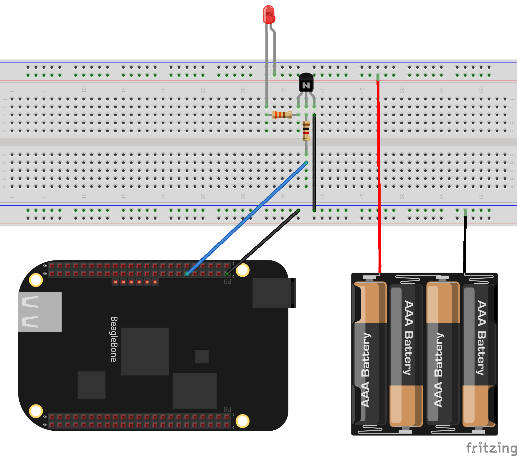
- Connect the battery pack to the + and - rails of the breadboard
- Connect the transistor's collector to the - rail of the breadboard.
- Connect the transistor's base to the 1k ohm resistor.
- Connect the transistors emitter to the 330 ohm resistor.
- Connect the LED's long lead to the + rail.
- Connect the LED's short lead to the 330 ohm resistor.
- Connect the Beaglebone's P9 pin 2 to the - rail.
- Connect the Beaglebone's P9 pin 12 to the 1k ohm resistor.
Next we will export the pin 12 ready for use.
echo 60 > /sys/class/gpio/export
Now we can turn on the LED by setting pin 12 to high.
echo high > /sys/class/gpio/gpio60/direction
and switch it off again by setting the pin to low
echo low > /sys/class/gpio/gpio60/direction
And that's it. We can now control the GPIO pin by writing either high or low to the direction file within the file system. Later tutorials will build upon this by manipulating the file system from a programming language such as Python or C++
By sure to add your comments below.
comments powered by Disqus