Interface the Beaglebone Black with the PCA9685 PWM controller
This tutorial shows how to control the PCA9685 PWM controller from a Beaglebone Black using Python. You will need the following items to follow along with this tutorial;
- A Beaglebone Black
- A 2A 5V power supply for the Beaglebone Black
- A PCA9685 board
- A 4xAA battery pack with batteries
- A standard hobby servo
- Four jumper wires (male one end female the other)

The PCA9685 PWM controller
The PCA9685 board is a 16 channel 12bit pulse width modulation (PWM) controller specifically optimised for LCD colour backlighting applications, but is also suitable for driving servos. It is controlled via an I²C interface, and by default is set to address 0x40. This address can be changed to any one of 64 possible addresses by linking the A0-A5 solder pads. However for ease, we will stick with the default address of 0x40.
The I²C bus.
The Inter-Integrated Circuit, refered to as i-squared-c (I²C), is a multimaster serial bus invented by Philips semiconductor division. It is used to connect low-speed peripherals to a motherboard, embedded system, mobile phone or other digital device. One advantage of the I²C bus is that it only requires two lines, one for the clock and one for data. This makes it very easy to interface with different devices.
The beaglebone black has three I²C busses, two of which are avaialbe to use on the IO breakout headers. The third I²C bus is reserved for interfacing with add on cape boards. However it can be accessed with a little re-configuration. We will use the P9 headers 19 and 20, which is the second I²C bus.
Connecting everything up
We need four jumper wires to connect the PCA9685 to the Beaglebone. First connect the 3.3v power on pins 1 and 3 on the beaglebone's P9 header to the Vcc and GND connections on the PCA9685. Then connect pin 19 on Beaglebone's P9 header to the SCL pin on the PCA9685. Finally connect pin 20 on the Beaglebone's P9 header to the SDA pin on the PCA9685.
Connect the servo to PWM channel 0 on the PCA9685. Servos usually have a red for +5V, a black wire for GND, then either a brown, yellow or white wire for the PWM signal. Connect the battery pack to the supply connection on the PCA9685 ensuring to connect the polarity the right way round. The black wire on the battery pack connects to GND and the red wire connects to V+. All the connections are shown here:
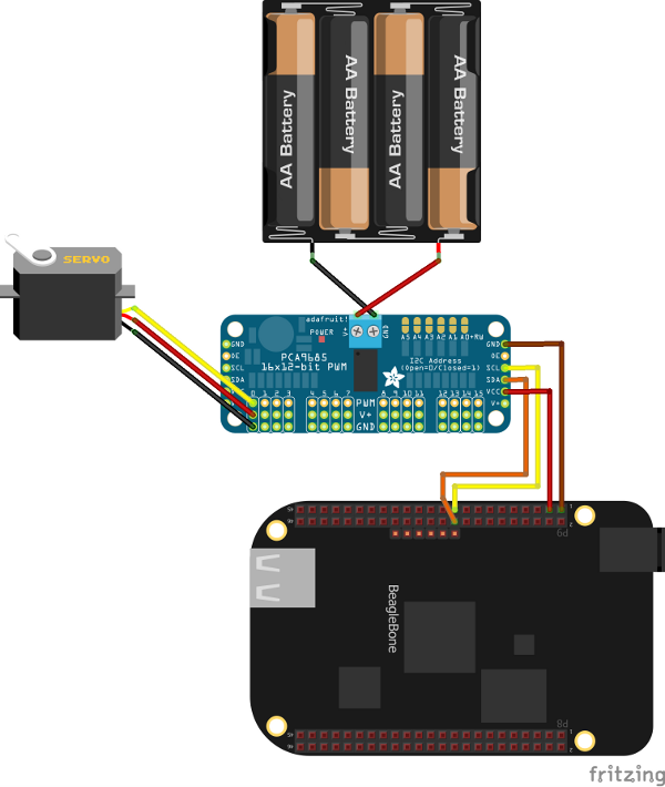
Finally power up the beaglebone by its 5volt barrel connection using the 2A 5V power adapter.
The i2c-tools package
i2c-tools is a linux package containing a set of tools that makes it easy to start experimenting with devices on the I²C bus. It allows us to perform tasks such a probing the I²C buses and reading and writing data. To Install i2c-tools on Angstom Linux we use the opkg package manager:
        opkg update
        opkg install i2c-tools
The first bus is number 0, and the second bus is number 1. So, you can probe the second I²C bus by typing:
i2cdetect -y -r 1
You should get an output similar to that shown here:
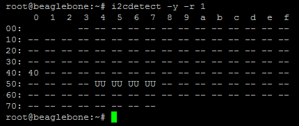
The important thing is that you see the PC9865 device shows up at address 0x40.
The Adafruit_BBIO Python libraries
We will use Adafruit_BBIO python library to make it easy to use the IO connections on the Beaglebone, and in particular I²C bus. Python is included with the Angstrom Linux image on the Beaglebone by default, but we need to install the Adafruit_BBIO libraries. To install these follow these simple steps:
/usr/bin/ntpdate -b -s -u pool.ntp.org
        opkg install python-pip python-setuptools pyton-smbus
        pip install Adafruit_BBIO
To make it easy to work with the PCA9685 board we borrow a file from the AdaFruit/Adafruit-Raspberry-Pi-Python-Code github repository. You can grab the file here http://goo.gl/oT0X5w. Just place a copy of it in your home directory for now. Ensure that the file is named Adafruit_PWM_Servo_Driver.py
Now create a file in your home directory on the beaglebone black called example.py and place the following code into it;
        #!/usr/bin/python

        from Adafruit_PWM_Servo_Driver import PWM
        import time

        # Initialise the PWM device using the default address
        pwm = PWM(0x40, debug=True)

        servoMin = 160  # Min pulse length out of 4096
        servoMax = 600  # Max pulse length out of 4096

        pwm.setPWMFreq(60)                        # Set frequency to 60 Hz

        while (True):
          # Move servo back and forward on channel 0
          pwm.setPWM(0, 0, servoMin)
          time.sleep(1)
          pwm.setPWM(0, 0, servoMax)
          time.sleep(1)
Finally get the Python interpreter to run this script with the following command:
python example.py
You should then see the servo rotates back and forth from its minimum and maximum positions. You may need to calibrate the code to the particular servo you are using by adjusting the servoMin and servoMax positions.
Hopefully this tutorial has provided you with the basic knowledge required to get started using the PCA9685 PWM controller with the Beaglebone Black. Please leave comments below to help me improve this tutorial.
comments powered by Disqus